Concept to Product - Our USBTINY Programmer
Here at Proto-PIC we are always thinking about new products we can bring to the market. Sometimes the ideas ‘just come to us’, other times, it’s a customer comment, review, or passing remark that inspires the idea. We had a customer who had a USBTINY programmer, and called for support on programming a couple of chips she had. The chips in question were the ATTINY 85, and the ATMEGA 328. While both of these chips are through-hole and easy to mount to a breadboard, our customer could not get the chips to program consistently.
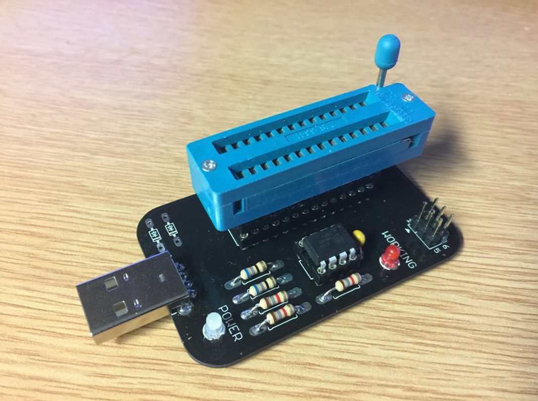
Thus, the idea of our USBTINY ISP ZIF programmer was born. The main idea was to produce a programmer with a ZIF socket that could program ATTINY25/45/85 as well as the ATMEGA 328 (As used in the Arduino). I also wanted to have an ICSP header to program chips ‘off board’.
Proof of concept.
The USBTINY firmware was downloaded from the internet, expecting this to require an ATTINY 84 Chip, I was happy to find the firmware could be compiled for an ATTINY 45, not a chip we normally have in stock, but if it works on a 45, it will work on an 85. Uploaded the compiled firmware to an ATTINY 85, and building the breadboard below, I tested the circuit by uploading firmware to another ATTINY 85.

We like RED at Proto-PIC
Seeing this program a chip for the first time gave me that 'happy' feeling inside. Now, I asked myself, do I make this a kit or do I create a PCB? Thinking that a finished product is more likely to be of use to the general tinkering community, I opted to create a PCB. I wanted to test this design with an ICSP setup, so I 'frankensteined' a board on a piece of matrix PCB board, and created :

FrankenProgrammer
He might be scary to look at, with his 'barely hanging on resistors' and you don't want to see the wiring on the back. But this programmer works 'It's ALIVE . . . . . ALIVE' , programming ATTINY 85s, ATMEGA 328s, and uploading the bootloader to the Arduino UNO. Now that I have a working prototype, time to layout & create a PCB.
To lay out the schematic, I referred to the breadboard prototype as this was easier to follow than FrankenProgrammer's wiring. I used EAGLE to layout the schematic & design the PCB, Knowing I wanted to use a ZIF socket, I laid out the circuit to allow me to use the same socket for the ATTINY 25/45/85 as well as the ATMEGA 8/168/328 chips. I find these the most popular chips to use in projects. I have also included an ICSP header, to program chips installed in boards with an ICSP header. Sending the design off to our PCB Fabricator, waiting for a week or so, for the PCBs to be made and delivered, and then finding out I had NO ZIF sockets left. No problem, I'll just install a swiss pin socket for testing.

A thing of beauty
Now that is a nice board - does need a small modification to the layout (The USB connector needs moved 1MM as it JUST clips the edge of the PCB), and as you can see, I added a place to add ZENER diodes if required, as well as a resonator to allow the programming of chips that have the fuses set to use an external oscillator. I did socket the ATTINY Chip that has the firmware, the reason for this was to allow me to remove for reprogramming if required. I think this is a good idea for the final release. I tested this board with an ATMEGA328, an ATTINY85, as well as programming a bootloader to an Arduino UNO. This programmer is now in my collection, and has a small upgrade of a ZIF socket (Mounted on Swiss Turned Pins).

In all her finery
Concept -> final design, around 3 weeks. Things went well for this design, It can take months, and take a few iterations to get a final design.
Recent Posts
-
What is Ohm's Law?
Are you curious about how electricity works? Let me introduce you to a very important concept i …9th Mar 2023 -
How do I control a central heating system using an Arduino
To control a heating system using an Arduino, you will need to write a sketch (program) that impleme …7th Feb 2023 -
The Versatility of Slotted Aluminium Extrusions: From Robotics to Camper Van Renovations
In today's ever-evolving world, the need for versatile and adaptable building materials is greater t …25th Jan 2023


